Thursday, April 12, 2018

Going low power with Banana Pi

April 12, 2018 Posted by Akalanka , No comments


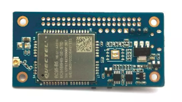
The Banana Pi is a great little board for building low power NB-IoT connected applications. Its small form factor and all in one design makes it easy to design a commercial product around it. In line with the last post on intro to low power design we will see how we can tweak and hack the Banana Pi to make it last years on a humble battery.

1. Remove power LED
In section 1.1 in the previous post we saw how the design should be optimized for low power. There is one glitch in this board in this department. The surface mount red colored LED that turns on when power is applied is a culprit which gulps down more than 500uA. You can desolder that LED and save 500uA very easily.

2. Remove linear regulator
In section 1.2 in our previous post we discussed how components should be selected carefully. The Banana Pi has a LM1117 linear regulator to convert the 5V power rail to 3.3V. Digging into the datasheet we found out the following

The quiescent current is the current that the regulator consumes even at no load. This is where the real robbery happens for the Banana. If you supply power via the USB port there will be a current consumption close to 5mA even when the microcontroller and modem are turned off. Even if you power up the board via the battery connector a reverse current will flow into the output terminals of the LM1117 which will consume around the same current. This is a design glitch that s expected to be resolved in future Banana versions. Till then, if you are going anywhere near low power design desolder the regulator and supply 3.3V power via the battery terminal. The downside is that you cannot now power the board via USB which means that if you want to program the microcontroller you have to supply power to the 3.3V battery terminal separately even though the USB is connected. Connect the USB, connect the 3.3V power and your Banana will get detected in your PC

3. Choosing the right power soruce 
The two main components in the Banana Pi are the microcontroller and the modem. The microcontroller can operate on any voltage between 2.0V and 3.9V. The modem can operate on any voltage between 3.3V and 4.2V Sadly, the Banana does not have any SMPS to up convert or down convert the voltage supplied to the battery in terminal. Therefore you have to careful in connecting a battery. The ideal battery voltage should be between 3.3V and 3.9V. It is safe to assume that you have to supply 3.3V so that everybody will be happy. The following options are available in the battery department.

3.1 Li-Ion cell
If you know about batteries you will know that a Li-Ion cell has a nominal voltage of 3.7V and can go up to 4.2V when fully charged. Therefore directly connecting a fully charged Li-Ion cell can spell out a death sentence for your Banana. If you want to run the Banana off a Li-Ion cell at least connect a Schottky diode in series so that when fully charged, the approx 0.25V forward drop will save the Banana. It is very naiive, inefficient and not professional at all and do not use diodes for dropping voltage unless when you are hacking. A better option would be to use a small buck converter (SMPS) to down convert the Li-Ion to 3.3V. You can get a small buck DC-DC converter like this for around $2 on ebay. Using an SMPS with a Li-Ion cell is a good option since cells are cheap and can be found in a variety of capacities.

3.2 Ni-MH battery
A Ni-MH cell has a nominal voltage of 1.2V. Therefore you will need at least 3 cells in series to keep the Banana working. Fully charged these cells go up to 1.25V which is still OK. Downside is that 3 Ni-MH cells are a bit bulky and it will be difficult to design a small form factor device. When compared with Li-Ion, Ni-MH has a lower energy density comparatively which makes it a bit inefficient space wise. However you can run the Banana with one Ni-MH cell if you use a buck-boost SMPS like this which is again around $2 on ebay. This SMPS converts any voltage between 0.8V and 6V to 3.3V. It can do this because it is a buck-boost converter which can up convert or down convert as required.

3.3 3V Coin cell (eg CR2032) or 2x1.5 cells (AA or AAA)
If you want to run the Banana's modem reliably you will need around 3.3V. Therefore you will again need the buck-boost converter to pump in 3.3V from these dry cells. The upside is that if you are designing a device which does not need rechargeable batteries you can go down this approach which will help to keep costs low. But remember these cells (specially CR2032) have lower capacities than typical Li-Ion and Ni-MH cells. Therefore you should be more careful about saving power.

3.4 LiFePo4 cell
It might be a bit more difficult to find this cell. I included this less poplar cell since it has a working voltage between 3.3V and 3.6V which fits in nicely to our requirement. You can avoid any SMPS DC-DC converters as well.

Battery technologies are a different black art which is not trivial at all. Calculating the battery life of a device is not as simple as dividing the average current consumption by the total battery capacity. Many factors such as the increase in internal resistance, ambient temperature should be considered in deriving an estimate.The fact that manufacturer stated capacities on most of the knock-off cells in the market are inaccurate does not make it any easier. Take a look at http://www.ganssle.com/reports/ultra-low-power-design.html#cr2032behavior for an in depth analysis of the CR2032 cell. There are some great research done on Li-Ion cells and Ni-MH cells as well. They are must look items if you designing a device running on such batteries.

However it is common sense that getting external power whenever possible is always preferred such as solar or any other energy harvesting method. I will try to cover this in the later post.

4. Lowering clock speed

The STM32F103 microcontroller can run typically up to 72MHz. You can even overclock it to 128MHz. But since we are low power dudes we are interested only in underclocking the processor.The following table in the reference manual in page 48 lists down the running currents at different clock speeds.Since our maple board configuration uses the external clock we are interested only in the top half of the table.

You can see that the current consumption goes down rapidly with the clock frequency. However it is not a trivial matter. The default maple configuration in your Arduino IDE is designed to run at 72MHz. It also offers 128MHz and 48MHz options. If you want to run at lower speeds you have to edit the board configuration and add your custom config. This is a bit tricky but not difficult. We tested the microcontroller at 12MHz and 3MHz and found significant reduction in power consumption. eg: at 3MHz the running current is around 6mA. In contrast at 72MHz the STM32 eats around 38mA! But due to the internal design of the microcontroller, you cannot use the USB for debugging (as COM port) at the 3MHz option since the USB needs a 48MHz clock to operate. For more info take a look at the clock tree in the reference manual. If you a hardware guy, lookup STM32cube tool by STMicroelectronics which will help you to adjust clock speeds without violating the compatibility requirements. Luckily we have done part of the work for you and all you need to do is edit the following files to add the 12MHz and 3MHz options.
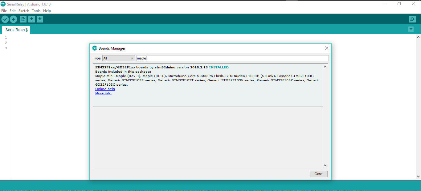
4.1 boards.txt
You can find this file in a location like C:\Users\lenovo\AppData\Local\Arduino15\packages\stm32duino\hardware\STM32F1\2018.2.13 Replace 'lenovo' with your username. Find out the "genericSTM32F103R" section and add the lines as shown below

4.2 boards_setup.cpp
This file is in a location like "C:\Users\lenovo\AppData\Local\Arduino15\packages\stm32duino\hardware\STM32F1\2018.2.13\variants\generic_stm32f103r8\wirish" In this file you have to do few modifications to let the compiler know of the new speeds you added in the boards.txt previously. 

  • Define the PLL Multiplier values for the new speeds

  • Setup the clock prescalers for the new speed

You can find the reference files at the Banana Pi GitLab at https://gitlab.com/akalankadesilva/bananapi


4. Going to low power modes whenever possible
The STM32 microcontroller in the Banana Pi has several low power modes as per its reference manual

Important things to note are:

  • Sleep mode: In this mode the CPU is turned off. But the RAM and all other peripherals receive power. Therefore your program variables are retained. The current consumption can be reduced to less than half of the running mode.
  • Stop mode: In this mode all 1.8V clocks are turn off as well as the main clock.
  • Standby mode: this is the lowest power mode. Since the voltage regulator is turned off you lose the content in the RAM. But since this microcontroller has an inbuilt RTC it also has a battery backup input. In this mode only the battery backup domain is operational. This includes the RTC and the backup registers. Therefore you have to store variables that should be preserved in the backup register area in this mode. In this mode we saw that the Banana consumed only 5uA ! This is the sleep current of both the microcontroller and the modem. This is a huge win in the power department for a device which is expected to run a long time on a battery.
Of course it goes without saying that network communication should be minimized and as much as possible to save power. Even though the dynamics of the modem is complex the user does not have to deal with any of that since NB-IoT handles power saving automatically. Simply put if you don't send anything you won't have to spend any power because the sleep current of the modem is few micro amps. We will see how the NB-IoT Tx and Rx cycles operate in detail in a future post.

Wednesday, April 11, 2018

Blockchain firsthand @ Google I/O 2018 with Mobitel

April 11, 2018 Posted by Akalanka 27 comments

Its that time of the year. The Google I/O, one of the largest tech gatherings in the world. So big that not only at the huge amphitheater at Mountain view California, thousands of tech enthusiasts gather to see whats latest by Google at extended events around the world. In 2017, the Google I/O event was live streamed as extended events in 534 locations globally. One such event was organized by Mobitel at Stein Studios with the participation of over two thousand tech gurus and geeks. Its back again and things will happen on the 8th of May at Stein Studios with the same glamour and glitz as last year. But this year Mobitel has tried to make things more interesting with blockchain.

Remember in the last post we learnt the basics of the blockchain? Now it is time to see a real life implementation of blockchain in all its glory. Mobitel has applied the blockchain technology to the process of registration and approval for Google I/O extended 2018 just so that you can have a first hand experience on how blockchain works. This is a great opportunity to learn even for the novice on how a real life application on how blockchain works.
In the last post we saw that blockchain is a distributed (stored in many many locations) immutable (cannot be changed) list of records. If you slow down and think a little you will realize that the registrations, ticket grants and such are all list of records with the participant details. For example the registration list is the list of participant details such as name, email, t-shirt size, food preference etc. Traditionally you can store this in a database or even an excel file without much problems. With blockchain, you store this list on the blockchain network. Any addition to the list is submitted to the network where it is updated. The list is publicly available and cannot be manipulated. Think of it like a distributed database which cannot be hacked. This is exactly how your registration details are stored when you register for Google I/O 2018 extended with Mobitel.

If you have entered the details for your registration in Mobitel's initial registration link, you will receive an email with the instructions needed to establish your smart contract based registration within the next couple of weeks. For example, this is what I got:

Important thing to note is the registration confirmation link in Step 2 which is unique to your email. Please do not share it with anyone else since this link is for one time use. If someone else uses your link for registration you will lose your chance to register.

Step1
The first step requires you to install uPort mobile app. You can find the app in Google Play or itunes for Apple. This is a generic open identity app for the Ethereum community and has no affiliation with Mobitel or Google. For more details visit https://www.uport.me/ Since your registration info is maintained in a blockchain, you need some form of a client app to  interact with the blockchain. Simply put, uPort to blockchain is like what a web browser is to the web. After installation follow few simple steps to get things started


uPort app contains your identity in the blockchain network. For those of you who are familiar with blockchain, you might find the information on the screenshot 6 interesting. It indicates that the app works on a non-commercial blockchain network. To be exact, it works on the Rinkeby Ethereum test network. This is where your registration details are stored.

Step 2
Now that you have a way to interact with the blockchain world, it is time to proceed with the registration. Click on the link that you got in step 2 in the email and click on the 'Complete Registration' button.

At this point you will be asked to login with uPort app. Open your uPort app and scan the QR code. You can find the QR code scan button on the upper left corner of your uPort app.
At this point your uPort app will request you to approve the login request with your identity in the blockchain network.

After clicking 'Continue' you can view the details of your registration entry (You might need to wait a couple of seconds after scanning the QR code for the 'Continue' button to become active). Remember, your details have still not been submitted to the blockchain network. Now it is time to create your smart contract for the Google I/O registration. To do so, click the 'Register button.

(Please note it might take for some time for the smart contract to get confirmed on the Rinkeby network.)

Congratulations! now you have successfully used a real world blockchain application. How can you be sure that its there in the blockchain? Simple. There is this great website called https://etherscan.io/ which is an online Ethereum block explorer. In layman terms it is a blockchain browser where you get to see smart contracts in the blockchain network. This is a public tool which has nothing to do with uPort or Mobitel. To view your smart contract etherscan.io, you need the transaction Id of your registration. Login to your google I/O registration again with your uPort app. Now you will be able to see that your registration is confirmed as seen below


Under your registration status, you can see a 'View your contract' button. Click on that and you will be redirected to etherscan.io where you can see your smart contract on the Rinkeby network.
If you don't speak geek, all this might sound gibberish to you. But hang on a sec, we'll try our best to explain whats what.

At the top you will see the transaction ID. You see every record added to the blockchain (always remember blockchain is a distributed list of records that cannot be changed) contains a transaction ID just like and entry ID. Sounds simple right? lets move on.

Next is the transaction hash. This is one of the primary parameters in ensuring the fundamental immutable property in the blockchain. It is basically a hash of the transaction details. If you are ready to dive deep there is this great couple of videos by a gentleman called Anders Brownworth https://www.youtube.com/watch?v=_160oMzblY8 and https://www.youtube.com/watch?v=xIDL_akeras along with a web resource https://anders.com/blockchain/blockchain.html It will make your life easy in getting to learn about the blockchain.

The next parameter 'Block Height' indicates how many blocks have been added to the chain after this transaction. The higher this number, the older the transaction and hence more secure it is from possible tampering(remember the immutable property)

Next few details are specific to the Ethereum network and it is very difficult to explain without going too technical. We'll try to have those debunked in a future blog post. However an interesting part is the last bit called 'Input Data'. At the end you can see the actual record details of the registration. So it proves that your record is stored in the blockchain network in a fully distributed fashion.
The record of your registration for Google I/O extended with Mobitel is now part of a distributed immutable list of records. Therefore there is no need to maintain a separate participant list for Mobitel. It is public and secure. You can use your uPort app to prove that you have obtained a ticket by pointing to the transaction of the ticket grant at the day of the event. This is a real life application of blockchain. 

Questions? Let me know in the comments section below!

Blockchain fast-tracked!

April 11, 2018 Posted by Akalanka 1 comment


Everyone has heard about it. Everyone thinks that others are doing it. But very few have actually done it. Yes we are talking about the blockchain! The internet if filled with explanations and interpretations about blockchain. Here's our take. A blockchain is a distributed list of records that is maintained in many machines across the internet. Think of it like the list of all the mischievous stuff you did at school. All the teachers and students know what you have done. There is no one place which contains your 'list'. Thus it is distributedYou have no way of altering what you have done. Everyone knows that it is you who spray painted the neighboring girl's school's wall. Thus it is immutable. Even if you try to spread a rumor that it was done by that guy you picked a fight with last term, it will soon get overwhelmed because people will only believe what a majority of their friends state. Thus any record cannot be altered without the consensus of the majority. 

In a nutshell- Blockchain gives you the ability to maintain a list of records in a distributed manner which cannot be manipulated by anyone easily. In contrast, how would you normally store a list of such records? In a central database in a server with strict security controls, which should work fine in many occasions. But going fully distributed using a technology like blockchain will unlock new opportunities for sure. 

One such is the Bitcoin. Money is something you do not trust with anyone for any reason whatsoever. Most of our monetary systems around the world depend on simple market dynamics such as demand and supply which are open but prone to subtle manipulations & unrelated charges. Blockchain makes it nearly impossible to do any manipulation which makes it a good candidate for handling monetary transactions. This is why crypto-currencies such as Bitcoin took the world by storm. It is this promise that led to a steep increase in the demand for Bitcoin and hence the huge peak.

The original creator of Bitcoin is a gentleman called Satoshi Nakamoto who published a paper on bitcoin. You can find the original paper by him at https://bitcoin.org/bitcoin.pdf which is pretty descriptive and surprisingly easy to understand. 
The world has moved on a lot since then. Ethereum foundation published their sophisticated app platform based on blockchain. It included a host of modifications to improve scalability as well as functionality. The term 'smart contracts' was coined during the same time since the new Ethereum platform paved the way to have programmable transactions. Simply put, smart contracts allow you to program payments, refunds etc. The fundamental properties of blockchain, coupled with programmable smart contracts open a large variety of use cases which were not possible or not very convenient previously. Therefore do not compare a present day use case which works nicely on a centralized system with a blockchain based approach and come to the conclusion that blockchain is an overkill. In many cases it would be an overkill. But there might be new applications with proper business models which might be well suited for blockchain. We will see in a later post how blockchain can be used for a ticket reservation system with a real use case.

Intro to low power design

April 11, 2018 Posted by Akalanka , No comments

Low power system design is a black art in electronics which is not for the faint of heart. It requires deep understanding on how digital circuits behave at the transistor level. However with embedded devices, in depth electronic knowledge is not the only requirement. Firmware development practices and overall solution design plays a major role in how long your device would last on 2xAA cells. It is very important to note that every microampere counts when you are designing a device that runs of a battery that you expect to last a couple of years. For in depth analysis on how low power systems work take a look at http://www.ganssle.com/reports/ultra-low-power-design.html which is a very elaborate and valuable resource. For those of you who are impatient, read on.

1. Hardware design

1.1 Design:
The hardware design of the development board plays a key role in deciding the power consumption. Following proper design practices and carefully selecting relevant components is key in keeping the power consumption to a minimum. 
Selecting the resistor for a simple pull down or pull up could decide how low you can go in the power department. Try to avoid connecting resistors such as the ones below as much as possible where there can be quiescent currents no matter how small. If unavoidable always use highest possible resistor values which will not impact your maximum operable frequency. 

Be careful about resistor dividers as well, especially what you find in power supplies to get the reference voltage. Those can be the culprits that draw several millamperes at standby even though they look innocent

Try to avoid using LED indicators such as power indicators as well, no matter how small. A typical surface mount LED consumes around 500 microamperes which works out to a staggering 4380mAh energy consumption for operating 1 year! If you want to have an indication on the operational status of the device, connect the LED to a microcontroller pin and blink it with a low duty cycle. 100ms ON and 10s OFF would reduce the previous 4380mAh annual requirement down to 43.8mAh!

1.2 Components:
Selecting the right components for the right job is obviously important. Common components/sub circuits that you might get wrong are

  • Power supplies- Never user linear regulators (I know that one is pretty obvious). They have a far lower efficiency than a typical SMPS converter. Another little known fact is most linear regulators have a operating quiescent current in the 1-5mA range which is HUGE when doing a low power design. This means that the regulator will gulp down that 3mA or whatever even when all your microcontrollers, modems are switched off which is nothing short of robbery. Therefore its best to stay away for linear power supplies. Even selecting a SMPS can also be challenging and try to avoid over-provisioning as much as possible.
  • Leaks and drains- Capacitors are another culprit that should be checked for leakage currents. If you do not operate at fast switching frequencies parasitic effects can be ignored. But a capacitor can have a insulation resistance which is sadly less than infinity as shown below which means that there can be a leakage current which is not zero. This is specially true for large electrolytic capacitors.

1.3 Microcontroller:
The microcontroller is a major power consumer. It is after all where all the stuff happens. The power consumption of the microcontroller can be minimized by following the below steps:
  • Go for a low power microcontroller whenever possible
  • Figure out the lowest clock speed that you can run your microcontroller. If you are not doing anything intensive, reducing the clock speed as much as possible with save you few tens of millamps. However if you are processing some data (eg: running a fast Fourier transform or a Kalman filter) you will need to strike a balance between running fast and completing the task quickly and going to sleep or running slow for a longer time.
  • Shutdown or disable unused peripherals in the microcontroller. Don't need ADC? disable the module. USB not needed? shut down that too. This will simply reduce the power consumption at the silicon level
  • Adjust I/O toggle frequency to a minimum possible value. Toggling I/Os fast is similar to running your processor at a high speed. All of this finally boils down to the switching loss in FETs. Check out the link https://www.eetimes.com/document.asp?doc_id=1278970 to see how the switching loss increases with clock speed.
  • Run your little micro at low voltage when possible. When the operating clock speed is reduced, the processor will run stably at low voltages which is a big win in the power department.
1.4 Modem:
The modem is usually THE biggest consumer of power in an IoT application. A modem has the following circuitry
  • RF transmit (Tx) and receive (Rx) components including the power amplifier for the Tx and the low noise amplifier for the Rx
  • RF baseband processor (usually a DSP) - this is where the nitty gritties related the radio layer will be handled
  • Application/ interface handling and command processing- This will be a processor which runs what we normally call the 'modem firmware'. 
As seen above there can be several DSPs (Digital Signal Processor) and co-processors inside a little modem which makes it eat power. But modern network technologies and modern chipsets are designed to be as efficient as possible when transmitting and consume almost no power at all during sleep modes which is a big win.

2. Firmware design

Writing the firmware should be done with the low power approach as a main focus. Few important points to remember are
  • Make sure that your code runs satisfactorily at low clock speeds. Compile your code in lower clock speeds and see how things go.
  • Try to finish the task as soon as possible and let the processor go to a low power mode. This can be stop, sleep or standby and these modes vary based on the microcontroller (this ones a no brainer!) Selecting the best mode can be tricky. If you plan to wake up in few seconds, the stop/suspend modes will be best while sleep or standby will be great if you plan to sleep for minutes or hours
  • Avoid restarting the modem unnecessarily. During each restart, the modem has to register on the network which takes a significant amount of Tx power for the radio. Newer network technologies like NB-IoT have optimized ways of keeping the modem connected to the network over long periods while conserving power. We will see how NB-IoT improves battery life in a later post.
We will see in our next post how Banana Pi can be hacked to minimize power consumption.


Tuesday, March 20, 2018

Peeling the Banana

March 20, 2018 Posted by Akalanka , , 1 comment
The banana PI is a tiny powerhouse with its powerful STM32 microcontroller and integrated NB-IoT modem. In this post we will go bit more in depth to see what this tiny board has on offer. 

Power source

The STM32F103RBT6 controller in the Banana should be powered from a stable voltage source between 2.0V and 3.6V. You can supply power via

  • USB connector from PC or power bank
  • Vcc GND pins in SWD header up to 3.6V
  • Battery connector up to 3.6V

The recommended operating voltage should be adhered to as indicated in the datasheet to keep the little STM happy.


I/O Pins
There are 51 I/O pins available in the STM32 and many of them can be found in the 40 pin GPIO header in the Banana. It the very important to note that not all pins are 5V tolerant. As indicated in the table above, the input voltage for 5V tolerant pins should be less than 5.5V. and only 3.3V for non 5V tolerant pins. The voltage levels of the peripherals connected to the I/O pins should be carefully checked to avoid damaging the STM32. It is always advisable to use a logic level converter for converting 5V to 3.3V or use peripherals that run off 3.3V to avoid destroying the microcontroller.

The 40 pin header layout is as follows:


When programming in Arduino IDE the pin name (eg:PC1) can be directly used in pinMode(), digitalWrite() and digitalRead() functions.

USART ports

The Banana has 3 USART ports in addition to the virtual USART port (USART0) which is visible over the USB when connected to the PC.

  • USART0 - virtual COMM port visible only when connected to PC via USB
  • USART1 - 5V tolerant
  • USART2 - Not 5V tolerant, used for modem communication and should be used with external devices
  • USART3 - 5V tolerant
I2C ports

The Banana has 2 I2C modules where both are 5V tolerant


SPI ports

The Banana has 2 SPI modules where SPI1 is only 3.3V but SPI2 is 5V tolerant

Onboard LEDs

The Banana has 4 on board LEDs for status indication etc.
  • LED1 - PC0
  • LED2 - PC1
  • LED3 - PC2
  • LED4 - PC3
Reset button
This button is self explanatory since it pulls the RESET pin low to reset the microcontroller

Power button
This button, even though named as the power button on the board pulls down the PD2 pin on the microcontroller when pressed. It is up to you to use it as a trigger or a power key in the firmware.


Sunday, March 18, 2018

NB-IoT with Inzpire

March 18, 2018 Posted by Akalanka , , 2 comments

Maintaining communication with remote devices is always a challenge in IoT. Building a IoT solution is always a new exercise because the types of hardware and protocols keep getting updated periodically. A good example is the Constrained Application Protocol (CoAP) which rose to popularity with small devices coming into the picture in Internet of Things. Today we will see how Inzpire can minimize the hassle of connecting your NB-IoT device with your application server.

Why CoAP?
Not all protocols are made the same way. CoAP is a very lightweight protocol optimized for low bandwidth networks. Unlike our good old HTTP which has been a reliable workhorse for more than 90% of our digital interactions with a very verbose protocol, CoAP has a compact packet format based on a binary protocol. Being an application layer protocol it relies on UDP transport for end to end delivery. However since guaranteed delivery is not a thing for UDP, CoAP implements its own simple stop-and-wait type error recovery and congestion control mechanism. If you know about the more sophisticated features offered by TCP such as adaptive flow control, think of CoAP like its slow cousin. But CoAP thrives in a resource constrained environment both on the network and device ends which gives it an edge over TCP in most narrow band applications. In tests we have seen that when operating at the coverage edge with NB-IoT, CoAP request with a 10 byte payload takes less than 3 seconds while a simple HTTP GET request takes in excess of 30 seconds (Yes you saw that right, its 30s, crazy stuff happen when you push the poor modem to the limit). I was initially skeptical on the effectiveness of CoAP, but the results of the above experiment made me think otherwise.

Inzpire to the rescue
Using CoAP comes with its own set of cons. A major one being the lack of experience needed to setup and maintain a CoAP server for device communication. Inzpire NB-IoT solves this problem for you by acting as gateway to forward CoAP messaging to and from HTTP. If you are familiar with how SMS and Voice works in Inzpire you will notice many similarities.


In this article we will see how you can connect your Banana Pi with a BC95 NB-IoT modem to your application through Inzpire NB-IoT. For more info on Banana Pi and NB-IoT refer the previous posts in this blog.

Step 1: Setup an HTTP/MQTT endpoint for device to communicate

HTTP method

You should have a HTTP web server running at a public location for handling up link messages from the device. Once a call is received by your short code or long number an HTTP request will be made from the Inzpire voice server to this server. The URL of this service should be entered in the callback URL in the next step when provisioning a NB-IoT device. The request will be a HTTP POST with the following parameters in a JSON formatted payload in the body
  • deviceId: This is the IMEI of the NB-IoT modem
  • payload:
    • type: data type is Buffer by default
    • data: data payload sent by the device as an array
MQTT method

If you are opting for the MQTT integration, you should have a public MQTT broker for this step. You will receive a publish from the device to the topic that you will provide in the next step. If you are subscribed to that topic with your own favorite MQTT client, you will be able to receive the message.

Step 2: Provision your Banana Pi in Inzpire

Provisioning an NB-IoT device in Inzpire is made extremely simple with a single SMS. 
  • HTTP Method:
    • Send NBReg<Space><IMEI of your Banana PI><space><Callback URL> to 77001
  • MQTT Method:
    • Send NBReg<Space><IMEI of your Banana PI><space><MQTT Broker URL><space><MQTT topic> to 77001
  • You will get a USSD prompt indicating that you will be charged a subscription fee for the service
  • Enter S in the USSD prompt and hit send
  • You will receive an SMS with 'Device registered successfully' with a device key.
Step 3: Connect your Banana-Pi , fire up Arduino IDE and start coding

Once your device is registered, simply call the functions related to messaging via CDP in the BC95-Arduino library at https://gitlab.com/akalankadesilva/BC95-Arduino to send messages and receive messages. All the messages that the device sends will be sent as HTTP POST requests to your callback URL.


Using BC-95 for NB-IoT

March 18, 2018 Posted by Akalanka , 4 comments
The BC-95 modem by Quectel is a low cost NB-IoT modem designed to be used in low power applications. This has a chipset by Neul whose parent company is now Huawei. Main highlights of this modem are:

  • Supports NB-IoT in Band 5/8/20
  • Inbuilt stack for UDP, COAP*
  • Support for Non-IP data delivery
  • Downlink max speed: 24kbps
  • Uplink max speed: 15.625kbps
  • AT Command interface via UART
The offered AT commands are quite comprehensive yet simple. You can refer the official page http://www.quectel.com/product/bc95.htm for more details. Important commands to remember are:

Basic AT commands:
  • AT+CFUN - turn modem ON or OFF by setting the functionality
  • AT+NRB - reboot modem
Network registration
  • AT+COPS - set network registration. 
  • AT+CEREG - check network registration status and parameters
Data (PDP) activation & testing
  • AT+CGATT - Attach packet data
  • AT+CGDCONT - set APN
  • AT+NPING - Ping a remote IP address
UDP Datagram 
  • AT+NSOCR - Open UDP socket
  • AT+NSOST - Send UDP message
  • AT+NSORF - Receive UDP Packet
  • AT+NSOCL - Close UDP Socket
CDP (COAP) 
  • AT+NCDP - Set CDP platform settings
  • AT+NMGS - Send CoAP message via platform
  • AT+NNMI - Received message indicator
  • AT+NMGR - Get received messages

A sample command sequence would be 
  • AT+NRB - Start with a reboot 
  • AT+COPS? - Check if connected to network
  • AT+COPS=1,2,"41301",7 - Make the modem attache to network manually. "41301" are the MCC & MNC for Mobitel Sri Lanka
  • AT+CGATT=1 - Start data session
Once this is complete you can either send UDP messages or CoAP messages using appropriate commands. 

Important: If the modem you have at hand is not registering on a network check the following - 
  • Enter AT+NCONFIG?
  • Check if the 'scrambling' parameter is set to false. If not enter
    • AT+NCONFIG="CR_0354_0338_SCRAMBLING","FALSE" 
  • Enter AT+NUESTATS to check the current modem status in the radio layer.
  • You can set the 'auto connect' parameter in NCONFIG to true so that once the modem is powered up it will auto attach to the network.
This is caused by the different ways the operators configure their network. Prior to 3GPP release 13 (R13) scrambling could be turned on on the network as an option. But R13 mandated turning on scrambling which meant the scrambling status should be configured depending on your NB-IoT service provider. However even this minor ambiguity is expected to be ironed out when complete R13 compliance is reached.

Connecting your BC-95 to Arduino

If you are using Arduino and want to connect to your BC-95, you are in luck. We have a simple Arduino library for you to give the head start at https://gitlab.com/akalankadesilva/BC95-Arduino 

Refer the bc95test.ino in the GIT for sample codes to send UDP messages and CoAP messages to remote servers. In the next post we will see how to communicate with a BC-95 based device using Inzpire NB-IoT device API.


Go bananas with Banana Pi!

March 18, 2018 Posted by Akalanka , , No comments
We went through the names of few NB-IoT modems currently available in the market in our last post. And then we laid our hands on this interesting piece of circuitry called the Banana Pi. If you are into the whole single board computer thing you might think its a raspberry pi knockoff. The initial banana pi is actually a single board computer similar to the raspberry pi and the orange pi (yes <fruit name> +pi is a naming convention for SBCs) with a ARMv7 processor running linux. Now Banana Pi is a popular brand in the industry and many different models with an array of ARM processors can be found. The banana pi we have  is not a single board computer, but a microcontroller board with a powerful STM32 series microcontroller. Turn it around and you will see a BC-95 NB-IoT modem in all its awesomeness.
To add to the excitement you will see that it has a 40 pin header for I/O pins and a battery terminal for directly connecting a 3.7V li-ion cell or couple of AA cells. All these are essential ingredients for a neat IoT device comes in a small 60mm x 30mm package.

In summary the Banana PI Linaro has
  • STM32F103R microcontroller running at 72MHz
  • 128kB program flash memory 
  • 20kB SRAM
  • 51 GPIOs
  • UART
  • I2C
  • SPI
  • PWM
  • BC95 NB-IoT Modem
  • 3.7V Li-Ion and 5V power input
  • 5 LEDs + 1 power LED
However the Banana Pi, with its STM32 microcontroller, poses few challenges to the developer unless you are familiar with IDEs like Keil and have access to a STLink programmer. If you are an Arduino fan and is now accustomed to the convenient way that things can get done with an Arduino, trying to learn programming the STM32 with Keil (which is an IDE for ARM based processors) might be intimidating. But the silver lining is that the good guys at Leaf Labs have an Arduino IDE compatible bootloader - Maple and the necessary IDE plugins - libmaple to get you up and running in no time. Let us see how you can setup the Banana Pi Linaro with your favourite Arduino IDE and Maple

Step 1: Install the Arduino board for STM32

In order to use your board with the Arduino IDE, the first step is to install the board definition.
  • Open your Arduino IDE. We tested this on 1.6.10
  • Go to Tools > Board > Board Manager
  • Search for 'Maple Mini' as shown below and install the STM32F1xx by stmduino board

When the board is installed, you will be able to see that there are few board definitions that are added as shown below.

Out of the newly installed boards, we are interested in the STM32F103R series, which is the tiny powerhouse we have in our Banana Pi. Like any other Arduino board you will also get the samples for the board under File >Examples >A_STM32_Examples


Step 2: Install Maple bootloader on microcontroller

If you are lucky enough to get your hands on a Banana Pi with Maple bootloader, you can skip this step. Else read on..
In order to flash a firmware to a microcontroller, usually you need a dedicated programmer for this task such as a PiCKit for PIC microcontrollers and AVR ISP for Atmel AVR microcontrollers. However an easier option is to use a bootloader. A bootloader is a small piece of code that runs for few seconds when the microcontroller is started to check for new firmware over Serial or USB and writes the new firmware to the program memory if available. Arduino has many different bootloaders available for AtMega 328, AtMega 2560 chips by Atmel such as Uno, nano, Mega, Diecimilia etc. in their boards. This makes it very convenient to program a microcontroller right from the IDE (such as Arduino) since it does not need a programmer hardware. All this time you have played with your Arduino, you have been using Atmel chips with Arduino bootloaders programmed via the Arduino IDE. A programmer is needed only to flash the bootloader, which needs to be done only once.

The STM32F103 microcontroller we have in our Banana Pi has its own method of firmware update using a special protocol called DFU. Device Firmware Update (DFU) is a standard protocol used to flash firmware updates to devices over USB. Most middle to high end microcontrollers have in built DFU for conducting firmware updates. The STM microcontroller in our Banana Pi has DFU and in built USB which enables it to flash firmware very easily. This is different to how things are done in an Arduino board with a ATMEL microcontroller where a USB-Serial bridge (FTDI232, PL2303 etc.) connects the host PC USB with the microcontroller USART0. This is because the ATMega 328 or ATMega 2560 microcontrollers in standard Arduino Uno, Nano or Mega boards (except the Leonardo) do not have in built USB ports. Therefore once you plug in the Banana Pi to the PC, it should be detected as a DFU device since DFU device drivers usually comes with any modern Windows OS. We will show how it can be done in Ubuntu in a later post. 

If what you read above sounded greek, fear not, as there is a easy way out. The maple bootloader enables you to use the STM just like an Arduino.To make an STM work with Arduino IDE with the board that we installed in the previous step, you should write the Maple bootloader to the STM which is a one time thing. You can find a good resource on how to install the Maple bootloader at Leaf Labs http://docs.leaflabs.com/docs.leaflabs.com/index.html You will need a STLink programmer for this process. Once the bootloader is flashed to the memory the DFU becomes active after a board reset for a short period for firmware update. If the IDE does not initiate a firmware update, the STM goes on to execute the program code. Now, the board will now be visible as a COM port in your PC just like an Arduino. 


Step 3: Setup Maple drivers on PC

Remember how we said that the board will be recognized as a DFU device by Windows? Most of the time you will need to introduce the drivers to the device in order to be recognized successfully. This is done using a simple tool called 'wdi-simple'. Refer this video https://www.youtube.com/watch?v=0jdJp3TQuJY for step by step instructions and this great github link https://github.com/rogerclarkmelbourne/Arduino_STM32/wiki/Maple-drivers for more info. Once the drivers are introduced properly, your Banana Pi will be fully functional for firmware update as well as Serial communication just like a our plain old Arduino Uno.